Azure Kinect has been released for over a year now and there are a lot of applications and researches utilizing this RGBD sensor to do amazing things. The benefits of using multiple sensors are well-explained by Microsoft here. Basically, live 3D reconstructions of a much larger scene, Tele-presence (which also is a seminar course at TUM where I am one of the tutors) are all possible thanks to that. The first problem you will encounter when setting up such a system is extrinsic calibration.
Overview
This article provides a basic approach (and code, of course) for extrinsic calibration that I hope to be helpful to you. This is a 2-step calibration approach:
- Estimate the camera pose by a fiducial marker.
- Refine the camera pose estimation by Iterative Closest Point (ICP).
Before we go into the details, there are some essential concepts that may help you understand better about this article.
What is Camera Extrinsics?
It is the transformation that describes the pose of the camera relative to the world. The pose consists of rotation and translation. So by doing extrinsic calibration, we can find where the camera is relative to a coordinate system that we defined in the world.
What is Fiducial Marker? AprilTag, ArUco, ChArUco?
Basically, it is an object that has certain kinds of patterns that can be easily detected by computer vision and used as a point of reference. In this case, we will use it to define the coordinate system of the world.
Commonly used markers in computer vision are AprilTag, ArUco, ChArUco, etc. OpenCV can detect ArUco, ChArUco, and a subset of AprilTag. I personally prefer to use AprilTag because it is still being updated and there is an iOS app that I can use to check the marker ID, orientation conveniently.


What is ICP?
A brief overview of the algorithm can refer to Wikipedia. In a nutshell, it iteratively finds the best transformation from a set of points to another set of points by minimizing the geometric distance.
Colored ICP is an ICP variant that utilizes both geometry and color information to perform point cloud registration. The details can be found in this paper. It is already implemented in Open3D and you can see how well it performs compared to the ICP that doesn’t use color.

Let’s do this!
Now that we are clear with these concepts, let’s start building the calibration tool.
First, let’s get the RGBD data from the mkv files. (Why offline? Because this can make our lives easier by not having the need to connect to the cameras all the time when you develop, try out and compare different algorithms) There is already a great example from Microsoft, so let’s grab that.
I try to make the core part of the calibration tool less dependent on a specific RGBD camera SDK, so let’s make a general container for the RGBD data.
struct FrameInfo
{
    // Color image
    std::vector<uint8_t> ColorImage;
    int ColorWidth = 0, ColorHeight = 0, ColorStride = 0;
    // Depth image
    std::vector<uint8_t> DepthImage;
    int DepthWidth = 0, DepthHeight = 0, DepthStride = 0;
    // IR image
    std::vector<uint8_t> IRImage;
    int IRWidth = 0, IRHeight = 0, IRStride = 0;
    // Point cloud data
    std::vector<int16_t> PointCloudData;
};
As an example, I can put the depth data to my data struct like this:
FrameInfo frame;
k4a_image_t images[3];
images[0] = k4a_capture_get_color_image(file->capture);
images[1] = k4a_capture_get_depth_image(file->capture);
images[2] = k4a_capture_get_ir_image(file->capture);
// Copy depth
frame.DepthWidth = k4a_image_get_width_pixels(images[1]);
frame.DepthHeight = k4a_image_get_height_pixels(images[1]);
frame.DepthStride = k4a_image_get_stride_bytes(images[1]);
const unsigned depth_size = frame.DepthStride * frame.DepthHeight;
frame.DepthImage.resize(depth_size);
const uint8_t* depth_image =  k4a_image_get_buffer(images[1]);
memcpy(frame.DepthImage.data(), depth_image, depth_size );
In order to create a point cloud image that is in the color camera coordinate system, we need to transform the depth image into color camera then reproject the depth image back to 3D points (x,y,z).
k4a_image_t transformed_depth_image = NULL;
k4a_image_create(K4A_IMAGE_FORMAT_DEPTH16,
                frame.ColorWidth,
                frame.ColorHeight,
                frame.ColorWidth * (int)sizeof(uint16_t),
                &transformed_depth_image)
k4a_image_t point_cloud_image = NULL;
k4a_image_create(K4A_IMAGE_FORMAT_CUSTOM,
                frame.ColorWidth,
                frame.ColorHeight,
                frame.ColorWidth * 3 * (int)sizeof(int16_t),
                &point_cloud_image))
k4a_transformation_depth_image_to_color_camera(file->k4a_transformation, images[1], transformed_depth_image)
k4a_transformation_depth_image_to_point_cloud(file->k4a_transformation, transformed_depth_image, K4A_CALIBRATION_TYPE_COLOR, point_cloud_image)
Now, exciting part!
AprilTag already provides a great example, so let’s grab that. And we only need to assemble a cv::Mat from our data struct to make it work:
cv::Mat image(frame.ColorHeight, frame.ColorWidth, CV_8UC4,
                  (void*)frame.ColorImage.data(),
                  cv::Mat::AUTO_STEP);
The pose estimation we get from AprilTag is the tag pose in color camera coordinate system, but we need to find the transformation between cameras to make it work with ICP. If we want to do ICP between the camera 0 and camera i, then we can do the following matrix multiplication:
tag_poses[camera_index] = transform;
const Eigen::Matrix4f tag_pose = tag_poses[0] * tag_poses[camera_index].inverse();
current_transform[camera_index] = tag_pose.cast<double>();
This will give us the transformation matrix between camera 0 and camera I, which is the matrix that we will fine tune. With the initial camera pose estimation ready, it is time for the second step.
However, if you remember, the point cloud we constructed only contains x ,y, z value but no color information. How do we do Colored ICP with no color? Well, let’s add the color information to our point cloud. One little note: OpenCV uses BGR representation and Open3D uses RGB for color.
for (int i = 0; i < count; i += coord_stride) {
    Eigen::Vector3d q{};
    q.x() = frame.PointCloudData.data()[3 * i + 0] / 1000.0f;
    q.y() = frame.PointCloudData.data()[3 * i + 1] / 1000.0f;
    q.z() = frame.PointCloudData.data()[3 * i + 2] / 1000.0f;
    if (q.z() == 0)
    {
        continue;
    }
    // BGR -> RGB
    Eigen::Vector3d color{};
    color.z() = (double)frame.ColorImage.data()[4 * i + 0] / 255.0;
    color.y() = (double)frame.ColorImage.data()[4 * i + 1] / 255.0;
    color.x() = (double)frame.ColorImage.data()[4 * i + 2] / 255.0;
    if (color.x() == 0 && color.y() == 0 && color.z() == 0)
    {
        continue;
    }
    full_cloud[idx]->points_.push_back(q);
    full_cloud[idx]->colors_.push_back(color);
}
Ok, now our point cloud is ready, let’s do the Colored ICP! Conveniently, an example is provided again! We just need to change it a little bit to suit our need for multiple point cloud registration.
And we are done! As you can see, I am just putting bits and pieces together, nothing state-of-the-art is happening here.

Bonus: Coordinate system conversion
As mentioned above, we are calibrating the extrinsics based on the color camera coordinate system. This figure from the official Azure Kinect document perfectly illustrated the difference between the depth and color coordinate system.
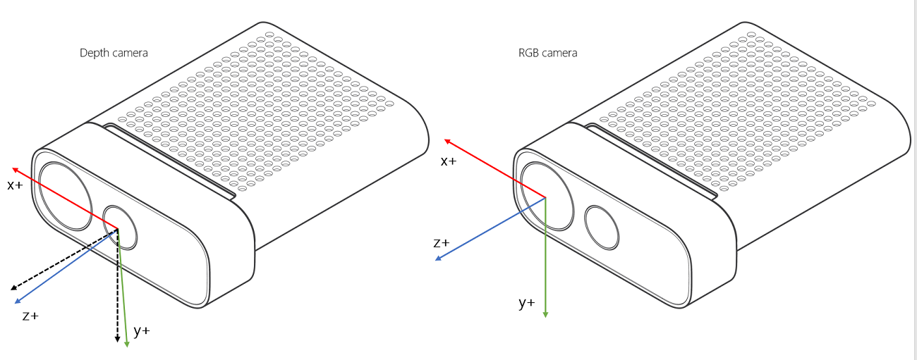
So if you want to transform everything into the depth camera system, you will need to do this:
// Transform to Depth camera coordinate
CameraCalibration calibration = frames[camera_index].Calibration;
Eigen::Matrix3f r_depth = Eigen::Map(calibration.RotationFromDepth, 3, 3).transpose(); // row major
Eigen::Vector3f t_depth = Eigen::Map(calibration.TranslationFromDepth, 3, 1) / 1000.0f; // in meters
t.rotate(r_depth);
t.translate(t_depth);
As you may notice, the coordinate system of Azure Kinect is a right-handed coordinate system, with z-axis pointing out of the camera, which is the same as OpenCV's (that’s why it works with the above steps). However, OpenGL or Unity uses different coordinate system and the figure from this blog summarizes them:

If you want to make it into OpenGL convention, you will need to do this:
// Flip y and z for OpenGL coordinate system
Eigen::Matrix4f yz_transform = Eigen::Matrix4f::Identity();
yz_transform(1,1) = -1.0;
yz_transform(2,2) = -1.0;
// Magic happens here
t.matrix() = (yz_transform * t.matrix() * yz_transform);
Full Code
Of course, there are a lot of code details I did not mention, like color conversion, data serialization, IMU-based tilt correction or centering scene around the marker. These concepts and approaches are not only applied to the Azure Kinect sensor, but also to all sorts of RGBD sensors. You can easily extend my calibration tool to work with other existing sensors like ZED, RealSense, etc. or any other new RGBD sensors in the future. I definitely welcome everyone to collaborate.
https://github.com/stytim/k4a-calibration
If this post helped you, please consider supporting me.

